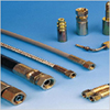
Hoses & Hose
Fittings
Size
The inside diameter of the hoses must be adequate to keep pressure loss to
a minimum and avoid damage to the hose arising as a result of heat
generation or excessive turbulence.
Hoses Outside Diameter can be a critical factor when hoses routing clamps
are used or hoses are routed through bulk heads.
Temperature
Both fluid and ambient temperature must be considered while selecting a
replacement assembly. The hoses selected must be capable to withstand
minimum and maximum temperature of system. While selecting hoses for its
maximum temperature, care should be taken that temperature stated is not an
intermittent value.
Applications
Determine where or how the replacement hose or assembly is used.
- Equipment Type: Most often only a duplicate of the original
hose will have to be made. Make sure all the requirements of the
applications are fulfilled. While selecting a hose, its application
should be considered I.e. Static / Moving / Flexing.
- Working Pressure: The working pressure or operating pressure
is one fourth of the hose minimum burst pressure
- Pressure Surges: In hydraulic systems, where pressure surges
are severe, increase the safety factor when selecting the proper hoses
(safety factor working / burst = 1/5) Conversely, in systems where
pressure surges are slight or non-existent, the normal safety factor
must be chosen.
- Environmental Conditions: Care must be taken to ensure that
the hoses and fittings are either compatible with or protected from the
environment to which they are exposed. Environmental conditions
including but not limited to ultraviolet heat, ozone, moisture, water,
salt water, chemicals and air pollutants can cause degradation and
premature failure and therefore must be considered.
- Mechanical Load: External forces can significantly reduce
hoses life. Mechanical loads which must be considered include excessive
flexing, twist, kinking, tensile or side loads, bend radius vibration.
Use of swivel type fittings or adaptors may be required to ensure no
twist is put into the hoses. Unusual applications may require special
testing prior to hose selection.
- Hose Construction: Various applications may require different
hoses construction.
Fluid to be conveyed
Hoses selection must assure compatibility of the hoses tube, cover,
reinforcement and fittings with the fluid use.
Pressure:
The system pressure should not exceed the mentioned working pressures.
Pressure spikes greater than the mentioned working pressure will shorten
hoses life. It is not recommended to use hoses on such applications.
- Pressure Drop: When pressurized media is flowing through the
hose, there is a certain amount of pressure difference between intake
and outlet points, this pressure difference is known as a; Pressure
Drop. This is due to gradual decrease in the pressure of the media along
the length. This aspect shall be considered while designing hoses
Type of End Fittings
Care must be taken to ensure proper compatibility exists between the hoses
and the end fittings.
| |
 |
|
Valves
valves are used in Hydraulic systems as very high pressure
hydraulic fluid to perform various functions. Huge amounts of energy can be
transferred over short distances much more efficiently with hydraulic
systems than with electrical systems, especially when the desired motion is
linear instead of rotational. A basic hydraulic system will have a pump, a
pressure control valve, one or more control valves, one or more pistons or
hydraulic motors that transfer the hydraulic power into motion and a return
system that collects the low-pressure hydraulic fluid and feeds it back to
the pump for re-use. See an illustration of this system in
Hydraulic Valves
Standard Testings
VE-LOCK Needle Valve is 100% tested with nitrogen gas at
1200psig (80 Bar) for leakage at seal & seal. Hydrostatic test performed
with pure water at 1 1/2 times of the working pressure. Other optional tests
like helium and temperature are available upon request.
VE-LOCK Manufactures High Pressure Hydraulic Valves which is utilize to
control Fluid Power & Motion in Piping Systems Hydraulic Valves are
mainly in to various Types Like , Check valves , Ball Valves , Flow control
valves , Needle valves & Manifold Valves. Hydraulic Valves can be use
for High Working Pressure up to 10,000 psi ( 700 BAR). Hyraulic Valves are
designed as per DIN /IS / SAE Standards as per its respective application in
the Piping Systems.
|
|

|
 |
|
|
|
Needle valves are small valves used for flow control in
liquid or gas services.The fine threading of the stem and the large seat
area allow for precise resistance to flow.
Needle valves have a slende, tapered point at the end of the vlave stem
that is lowered through the seat to restrict or block flow. Fluid flowing
through the valve turns 90 degrees and passes through an orifice that is the
seat for a rod with a cone shaped tip. These small valves are widely used to
accurately regulate the flow of liquids and gases at low flow rates. The
fine threading of the stem and the large seat area allow for precise
resistance to flow. Needle valves are used to control flow into delicate
guages,which might be damaged by sudden surges of fluid under pressure.
Needle valves are also used in situations where the flow must be gradually
brought to a halt,and at other points where precise adjustments of flow are
necessary or where a small flow rate is desired. They can be used as both
on/off valves and for throttling services.
Needle valves are often designed with a metal needle valve (generally
brass,bronze,or stainless or other alloys of steel) and an elastomeric seat
(generally PVC,CPVC,PTFE,or a wide range of brand name plastics and
thermoplastics. ) While this is the most common form,valves are available
that have metal - metal,plastic - plastic,or plastic- metal needles and
seats. These variations are usually designed with specific applications in
mind, especially situations where corrosion,high or low temperatures or
extensive wear are possible. In such cases,it is best to consult with the
manufacturer ti find which type of valve is best for the application at hand
Needle valves are used in almost every industry in an incredibly wide range
of applications - anywhere control or ,etering of steam,air,gas,oil,water or
other non - viscous liquids is required. They can be found in every industry
from aerospace to zoological science,every service from gas and liquid
dispensation to instrumentation control cooling to power generation.
However,needle valves should be avoided in applications where the media is
viscous,or in the dispensation of slurries.The small flow orifice can easily
trap thick materials or solids and become blocked.
Needle valves are widely used for severe service operation as regulating
and shut - off valves in many critical high pressure as well as vacuum
application on fluid line connections like Natural gas lines,Gas sampling
lines Test benches,Control panels,Instrument Air lines Hydraulic power
systems Flow meters,manifolds Drain,Vents, Pressure gaugesand Transmitters
Etc.
Design Features
- Pressure up to 6000psi (412)bar.
- Temperature from 70T (21"C) to 450T / 232 0 C / with standard
TFE packing and up to 1200 0 F with optional Grafoil packing.
- Orifice size of 0.156" (3.962) to 0.437" (11.0998).
- Choice of soft seat,V and ball Tip stem design.
- Straight and angle pattern.
- Many combinations of end connections.
- Full raw material traceability,Testing & Identification.
 |
 |
 |
 |
|
MINIATURE TYPE - FORGED
MALE x FEMALE END |
MINIATURE TYPE
SCREWED END |
MINIATURE TYPE
ANGLE END |
INTEGRAL BONNET
MALE x FEMALE END |
 |
 |
 |
 |
|
SCREWED BONNET
OD x OD END |
UNION BONNET TYPE
SCREWED END |
ROUND BODY
MALE x FEMALE END' |
TUBE OD TYPE
METRIC / INCH OD |
 |
 |
 |
 |
|
SOLID BAR STOCK
GENERAL PURPOSE |
GENERAL PURPOSE
SCREW END |
BLOCK & BLEED
MALE x FEMALE END |
|
Standard Testings
VE-LOCK Needle Valve is 100% tested with nitrogen gas at 1200psig
(80 Bar) for leakage at seal & seal. Hydrostatic test performed with
pure water at 1 1/2 times of the working pressure. Other optional tests like
helium and temperature are available upon request.
Ball Valves - 2 way type / 3 way type |

|
 |
|
|
|
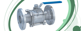
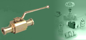
Ball valves are quarter - turn, straight through flow
valves that have a round closure element with matching rounded seats that
permit uniform sealing stress. Ball valves are used in situations where
tight shut - off is required. The type of seat can vary with the valve
pressure rating and material of construction.Some valve seats are composed
of single molded forms,while other seats with higher - pressure rating often
incorporate a trunnion design where each face of the ball is separately
sealed. They are wide duty valves,able to transfer gases,liquids and liquids
with suspended solids (slurries).
In general,ball valves offer many advantages when contrasted with other
valve types.They provided superior ease of operation and can maintain and
regulate high volume,high pressure and high temperature flow. Most common
ball value offer rugged construction providing for a long service life,and a
comparably low cost.Additionally,the design of the regulating element allows
the valve to function without the complication of side loads,typical of
butterfly or glode valves and the valve design permits inspection and repair
of seats and seals without removing the valves' body from the line.
Ball vlaves are available in a variety of body styles,including one -
piece, two - piece,three - piece and flanged body construction.
Each of these ball valve forms offers specific advantages depending upon
the requirements of the given application.Similarly, they are designed using
a wide varriety of materials,as required by their application. Common ball
valve materials include brass, bronze,copper,castiron,ductile iron,stainless
and other steel types,metal alloys and plastics including PVC and CPVC. It
is best on consult with the manufacturer for the specific properties of the
materials used in the valve,and how this relates to the application that
include type,concentration and temperaturer of the media being handled.
Standard Testings
VE-LOCK Ball Valves is 100% tested with nitrogen
gas at 1200psig (80 Bar) for leakage at seal & seal. Hydrostatic test
performed with pure water at 1 1/2 times of the working pressure. Other
optional tests like helium and temperature are available upon request.
 |
 |
 |
 |
|
ANGLE BALL VALVE
FEMALE x FEMALE END |
BALL VALVE
SCREWED END |
GENERAL PURPOSE
SCREWED END |
GENERAL PURPOSE
SCREWED END |
 |
 |
 |
 |
|
3 WAY BALL VALVE
OSCREWED END |
FLANGED END
SOCKET WELD TYPE |
FLANGED END
TUBE OD TYPE |
SOLID HEX BAR
LOW COST VALVE |
 |
|
ROUND FLANGED END
NB SIZES |
|
|
|
Check Valve ( non return valve) |

|
 |
|
|
|
Check valves are self - activating safety valves that
permit gases and liquids to flow in only one direction,preventing process
flow from reversing. They are classified as one - way directional valves.
Fluid flow in the desired direction opens the valve, while backflow forces
the valve closed. The mechanics of check valve operation are relatively
simple.Most check valves contain a ball that sits freely above the
seat,which has only one through hole. The ball has a slightly larger
diameter than of the through hole. When the pressure behind the seat exceeds
that above the ball,liquid is allowed to flow through the valve;however
,once the pressure above the ball exceeds the pressure below the seat,the
ball returns to rest in the seat,forming a seal that prevents backflow.
Check valves use a variety of technologies to allows and stop the flow of
liquids and gases.Single - disc swing valves are designed with the closure
element attached to the top of the cap. Double - disc or wafer check -
valves consist of two half - circle disks hinged together that fold together
upon positive flow and retract to a full - circle to close against reverse
flow. Lift check valves feature a guided disc. Spring - loaded devices can
be mounted vertically or horizontally.Silent or center guide valves are
similar to lift check valves,with a center guide extending from inlet to
outlet ports. The valve stopper is spring and bushing actuatedto keep the
movement "quite". Ball check valves use a free floating or spring
loaded ball resting in a seat ring as the closure element. Cone check valves
use a free floating or spring loaded cone resting in the seat ring as the
closure element.
Selecting check valves requires an analysis of performance
specifications,materials of construction,connection types, and
media.Performance specifications include valve size,pressure rating,media
temperature,and valve flow coefficient. Most check valves are made of acetal
polymers,aluminum,brass,bronze,cast iron,chlorinated polyvinyl chloride
(CPC), ductile iron,copper,polyethylene(PE),polypropylene
(PP),polytetrafluoroet (PTFE),polyvinyl chloride (PVC),polyvinylidene
fluoride (PVDF), rubber steel,or stainless steel.Connections for check
valves can use threads,compression fittings,tube fittings,bolt flanges,clamp
flanges,butt welds,socket welds,and union connections.In terms of
media,check valves are rated for air,compressed air water ,hot water , cold
water,potable water,salt water,wastewater,gasoline,diesel fule,high- purity
gas,liquefied petroleum gas (LPG) natural gas,sour gas,corrosive
gas,abrasive material,acids,corrosive chemicals, adhesives,
concrete,grout,coolants,hazardous materials,high viscosity fluids,hydraulic
fluids,liquid metal,lubricants,oil, powders,solids,rendering
wastes,sludge,slurry,ash slurry , or steam.
Standard Testings
VE-LOCK Check Valves is 100% tested with nitrogen
gas at 1200psig (80 Bar) for leakage at seal & seal. Hydrostatic test
performed with pure water at 1 1/2 times of the working pressure. Other
optional tests like helium and temperature are available upon request.
 |
 |
 |
 |
|
CHECK VALVE - SCREWED END -SINGLE PIECE |
CHECK VALVE - TUBE OD END |
CHECK VALVE - SCREWED END -TWO PIECE |
INSTRUMENTATION CHECK VALVES -TYPES |
 |
 |
 |
 |
|
CHECK VALVE - SCREWED END - RHDI |
CHECK VALVE - TUBE OD END -RHD |
CHECK VALVE - TUBE OD x MALE - RHZ-R -ED |
CHECK VALVE - TUBE OD x MALE - RHV-R -ED |
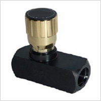
Technical Selection
- NPT & SAE Connections
- Carbon Steel With Black Oxide Plating
- Set Screw Allows Knob to be Locked into Position
- Graduated Knob & Spindle for Accurate Flow Control
- 7 PSI Standard Spring Setting
- Buna O-Ring/PTFE Stem Packing
- Temperature Range - 4° F to + 176° F
Standard Testings
VE-LOCK Flow Control Valves is 100% tested with
nitrogen gas at 1200psig (80 Bar) for leakage at seal & seal.
Hydrostatic test performed with pure water at 1 1/2 times of the working
pressure. Other optional tests like helium and temperature are available
upon request.
 |
 |
|
FLOW CONTROL VALVE (WITH NRV) |
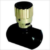
MTHROTTLE VALVE (WITH OUT NRV) |
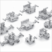 Design Features
- Forged one piece body construction for higher strength.
- Two isolation and one equalizing valve for instrument balancing
applications.
- Metal to metal body bonnet seal for higher pressure and temperature
sealing.
- Temperature rating - 50° C To 230° C.
- Mounting holes are standard to allow easy fixing to pipe stands and
enclosure.
- Non rotating Vee/ Ball tip design.
- Full material traceability.
- Material of construction can be supplied to meet the requirement of
NACE MR - 01 -75
Standard Testings
VE-LOCK Manifold Valves is 100% tested with
nitrogen gas at 1200psig (80 Bar) for leakage at seal & seal.
Hydrostatic test performed with pure water at 1 1/2 times of the working
pressure. Other optional tests like helium and temperature are available
upon request.





 Design Features