


 |
 |
 |
 |
 |
manufacturer of high quality Tube Fittings That's |
 |
|
|
 |
 |
TWIN FERRULE BITE TYPE FITTINGS |
|
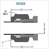
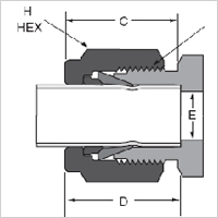
| INCHES | ||||||
| VE-LOCK | D TUBE | |||||
| SIZE | TUBE | STRAIGHT | H | E | INS. | |
| NO. | O.D. | THREAD | C | HEX | DIA | DEPTH |
| 1 | 1/16" | .10-32 | 43 | 5/16" | 52 | 34 |
| 2 | 1/8" | .5/16-20 | 60 | 7/16" | 93 | 50 |
| 3 | 3/16" | .3/8-20 | 64 | 1/2" | 125 | 54 |
| 4 | 1/4" | .7/16-20 | 70 | 9/16" | 187 | 60 |
| 5 | 5/16" | .1/2-20 | 73 | 5/8" | 250 | 64 |
| 6 | 3/8" | .9/16-20 | 76 | 11/16" | 281 | 67 |
| 8 | 1/2" | .3/4-20 | 87 | 7/8" | 406 | 90 |
| 10 | 5/8" | .7/8-20 | 87 | 1" | 500 | 96 |
| 12 | 3/4" | .1-20 | 87 | 1-1/8" | 625 | 96 |
| 14 | 7/8" | .1-1/8-20 | 87 | 1-1/4" | 750 | 1.03 |
| 16 | 1" | .1-5/16-20 | 1.05 | 1-1/2" | 875 | 1.24 |
| 20 | 1.1/4" | .1-5/8-20 | 1.52 | 1-7/8" | 1.09 | 1.61 |
| 24 | 1.1/2" | .1-15/16-20 | 1.77 | 2-1/4" | 1.34 | 1.96 |
| 32 | 2" | .2-5/8-20 | 2.47 | 2-3/4" | 1.81 | 2.65 |
 |
 |
| MILLIMETERS | ||||||
| VE-LOCK | D TUBE | |||||
| SIZE | TUBE | STRAIGHT | H | E | INS. | |
| NO. | O.D. | THREAD | C | HEX | DIA | DEPTH |
| 2 | 2mm | .5/16-20 | 15.3 | 12 | 1.7 | 12.9 |
| 3 | 3mm | .5/16-20 | 15.3 | 12 | 2.4 | 12.9 |
| 4 | 4mm | .3/8-20 | 16.1 | 12 | 2.4 | 13.7 |
| 6 | 6mm | .7/16-20 | 17.7 | 14 | 4.8 | 15.3 |
| 8 | 8mm | .1/2-20 | 18.6 | 15 | 6.4 | 16.2 |
| 10 | 10mm | .5/8-20 | 19.5 | 18 | 7.9 | 17.2 |
| 12 | 12mm | .3/4-20 | 22 | 22 | 9.5 | 22.8 |
| 14 | 14mm | .7/8-20 | 22 | 24 | 11.1 | 24.4 |
| 15 | 15mm | .7/8-20 | 22 | 24 | 11.9 | 24.4 |
| 16 | 16mm | .7/8-20 | 22 | 24 | 12.7 | 24.4 |
| 18 | 18mm | .1-20 | 22 | 27 | 15.1 | 24.4 |
| 20 | 20mm | .1-1/8-20 | 22 | 30 | 15.9 | 26 |
| 22 | 22mm | .1-1/8-20 | 22 | 30 | 18.3 | 26 |
| 25 | 25mm | .1-5/16-20 | 26.5 | 35 | 21.8 | 31.3 |
| Table 9 | ||||
| Material | Type | ASTM Tubing Spec | Condition | Max.Recommended |
| Hardness | ||||
| stainless Steel | 304,316,316L | ASTM A 269,A 249, | Fully Annealed | 90 Rb |
| A 213,A632 | ||||
| Copper | K or L | ASTM - B75 | Soft Annealed | 60 Max |
| B68, B88 (K or L) | Temper 0 | rockwell 15 T | ||
| Carbon steel | 1010 | SAE -J524b,J525b | Fully Annealed | 72 Rb |
| ASTM-A-179 | ||||
| Aluminum | Alloy 6061 | ASTM B-210 | T6 Temper | 56 Rb |
| Monel | 400 | ASTM B-165 | Fully Annealed | 75 Rb |
| Alloy C-276 | C - 276 | ASTM -B - 622,B - 626 | Fully Annealed | 90 Rb |
| Alloy 600 | 600 | ASTM B -167 | Fully Annealed | 90 Rb |
| Carpenter 20 | 20CB - 3 | ASTM B -468 | Fully Annealed | 90 Rb |
| Titanium | Commercially | ASTM B - 338 | Fully Annealed | 99 Rb |
| Pure Grade 2 | 200 Brinell Typical | |||
 |
 |
 |
 |
|
BULKHEAD COUPLING |
EQUAL CROSS |
MALE RUN TEE |
REDUCING UNION COUPLING |
 |
 |
 |
 |
|
EQUAL UNION COUPLING |
EQUAL ELBOW COUPLING |
EQUAL UNION COUPLING |
ACCESSORIES |
ADAPTOR THREAD FITTINGS |
|
| THREAD TYPE | STANDARD USED AS | AVAILABLE MOC = MATERIALS | |||
| BSPP | ISO 228 - 1G | STEEL / STAINLESS STEEL / BRASS | |||
| BSPT | ISO 7/1 ,JIS B 0203 | STEEL / STAINLESS STEEL / BRASS | |||
| NPT | SAE J 476 ,ANSI B1.20.3 | STEEL / STAINLESS STEEL / BRASS | |||
| JIC | STEEL / STAINLESS STEEL / BRASS | ||||
| UNF | STEEL / STAINLESS STEEL / BRASS | ||||
| METRIC | DIN 2353 - ISO 8434 -1 | STEEL / STAINLESS STEEL / BRASS | |||
 |
 |
 |
 |
|
HEX / HOSE ADAPTOR |
ADAPTOR - MALE x FEMALE(SW) |
ADAPTOR - SW (F) x (F) |
MALE ELBOW |
 |
 |
 |
 |
|
FEMALE SWIEVEL ELBOW |
ELBOW - MALE x FEMALE (SW) |
MALE x FEMALE ELBOW |
ELBOW - FEMALE x FEMALE |
 |
 |
 |
 |
|
VSTI / ALLEN PLUG WITH ED |
HEX MALE PLUG |
MALE TEE |
FEMALE (SW) TEE |
 |
 |
 |
 |
|
BRANCH (SW) TEE |
SWIEVEL FEMALE PLUG |
SOCKET - FEMALE x FEMALE |
RI -REDUCE MALE x FEMALE |
 |
|||
|
RI -REDUCE MALE x FEMALE |
JIC 37 FLARE FITTINGS |
|
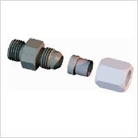 VE-LOCK represents the JIC 37 Flare Fitting concept since year 1994
and the design has since gained worldwide acceptance due to its many
inherent features and customer benefits. Today,the JIC 37 Flare Fitting is
the most widely used fitting in the world. Its appeal is in its simplicity,
compact design, ease of assembly, reliability (single seal), material
availability, adaptability to inch or metric tube, worldwide availability
and acceptance. Further helping its acceptance is its widespread use as a
hose Adaptor.
 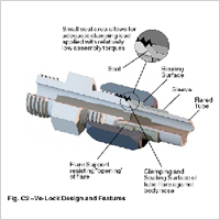 The VE-LOCK (JIC 37 Flare Fitting) design is simple. It uses an
easily produced flare at the tube end to seal and hold fluid under high
pressure. The fitting consists of three pieces : the body, sleeve and nut.
The tube end is flared at a 37 ° angle (74 0 include angle) and held
between the fitting nose (seat) and the sleeve (support) with the nut as
shown in Fig.C2,providing a very effective (single) seal between the fitting
nose and the tube flare.
 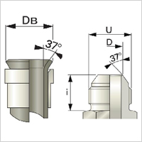 The
primary difference between a two -piece flare fitting and the three - piece
design is the flare support sleeve. The support sleeve provides several key
functions:
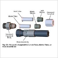 Study
the following example illustrating the options with an SAE -8 (1/2")
VE-LOCK fitting:
 |
 |
 |
 |
|
JIC FLARE FITTINGS |
JIC MALE CONNECTOR |
JIC EQUAL ELBOW |
JIC EQUAL TEE |
 |
 |
 |
 |
|
JIC EQUAL UNION |
JIC NUT & FERRULE |
JIC HEX PLUG |
JIC BULKHEAD ELBOW |
 |
 |
||
|
JIC BULKHEAD UNION |
JIC SWIEVEL ELBOW |